
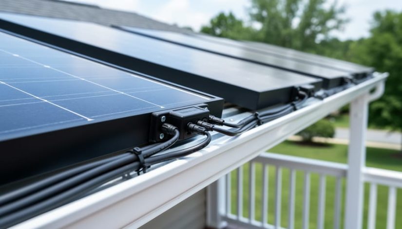
How to Wire 2 Solar Panels in Series: Step-by-Step Connection Guide
Connecting two solar panels in series is straightforward: you join the positive terminal of one panel to the negative terminal of the second panel, doubling your system voltage while keeping amperage constant. This configuration takes about 30 minutes for most DIYers with basic electrical knowledge and requires only a few simple tools and safety precautions.
Series wiring makes sense when your charge controller or inverter requires higher input voltage than a single panel provides. If you’re working with standard residential panels producing around 40 volts each, wiring them in series gives you roughly 80 volts to work with. That higher voltage reduces line losses over longer wire runs and matches the input requirements of many modern grid-tie and battery systems.
The beauty of series connections lies in their simplicity. You’re essentially creating one continuous electrical path, much like connecting batteries end-to-end in a flashlight. The latest solar tech has made panel compatibility even easier, but the fundamental wiring principles remain unchanged.
Before you climb on your roof or head to your ground mount location, understanding what happens electrically will help you wire confidently and troubleshoot effectively. Your panels will perform as one unit, so proper connections matter. A loose terminal or reversed polarity won’t just reduce efficiency; it can prevent your system from working altogether.
This guide walks you through everything from gathering the right materials to verifying your connections are producing the expected voltage. Whether you’re expanding an existing array or building your first small off-grid setup here in North Carolina, you’ll learn the exact sequence of steps that ensures a safe, functional series connection.
Understanding Series Wiring for Solar Panels
Series vs. Parallel: When to Choose Series
When wiring two solar panels, you have two fundamental options: series or parallel. In series, you connect positive to negative, which adds the voltage of both panels while keeping amperage the same. If each panel produces 18 volts at 5 amps, a series connection gives you 36 volts at 5 amps. Parallel wiring does the opposite, it connects positive to positive and negative to negative, maintaining voltage while doubling amperage.
Series configuration works best in several specific situations. If you’re running cables over long distances from your panels to your charge controller or inverter, series wiring reduces power loss because higher voltage allows you to use smaller gauge wire. This is particularly valuable for roof-mounted systems where wire runs can exceed 50 feet. Series also matches the requirements of many modern grid-tie inverters and 24-volt or 48-volt battery banks, which need higher input voltages to operate efficiently.
Choose parallel wiring when you need to maintain lower system voltages, match the requirements of a 12-volt battery system, or when your panels might experience uneven shading throughout the day. Understanding these electrical fundamentals is part of green energy education that helps you design a system matched to your actual power needs rather than following generic installation templates.
Tools and Materials You’ll Need
Before you start connecting your solar panels, gather everything you’ll need. Having all tools and materials on hand prevents mid-project trips to the hardware store and ensures a safer, more efficient installation. The right equipment makes the difference between a professional-grade connection and one that could fail when you need it most.
Here’s your complete checklist:
- Two solar panels of matching voltage and wattage specifications
- MC4 connectors (if not pre-installed on your panels)
- MC4 crimping tool for secure connector installation
- Solar-rated PV wire, typically 10 AWG or 12 AWG depending on your system amperage
- Digital multimeter capable of measuring DC voltage up to 100V
- Wire strippers designed for 10-14 AWG wire
- Wire cutters or diagonal pliers
- Cable ties or UV-resistant zip ties for wire management
- Insulated gloves rated for electrical work
- Safety glasses
- Optional: Heat shrink tubing for additional connection protection
- Optional: Label maker or weatherproof tags for marking polarity
When selecting wire, choose solar-rated cable designed for outdoor exposure and UV resistance. Standard household electrical wire isn’t built for the conditions your solar array will face. For most two-panel residential setups, 10 AWG wire handles the current safely, but verify your specific panel amperage.
MC4 connectors are industry-standard for solar installations because they’re weatherproof, lockable, and designed specifically for DC solar applications. Pre-assembled connectors save time, but learning to crimp your own gives you flexibility for custom wire lengths.
While premium tools can add to your upfront commercial solar cost or residential project budget, they’re worth the investment if you plan additional solar work. Quality crimpers and multimeters last decades and ensure reliable connections every time.
Safety Precautions Before You Begin
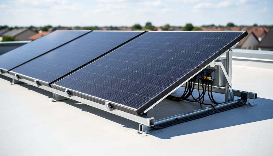
Before you start connecting solar panels, understand that you’re working with DC voltage, which can deliver a serious shock even in daylight. Unlike household AC power, DC current doesn’t let go, it can cause your muscles to contract and hold onto the source. Two panels in series will double your voltage output, so a pair of 12-volt panels produces 24 volts, and higher-voltage panels will generate even more combined power.
Start by turning off any connected charge controllers or inverters before you touch the panels. Wear rubber-soled shoes and insulated gloves rated for electrical work. Keep a dry workspace, water and electricity create deadly combinations. According to Solar electrical shock hazards guidance, you should never work alone on solar installations. Have someone nearby who can call for help if something goes wrong.
Check your panels for any damaged wiring, cracked glass, or exposed conductors before you begin. If you see physical damage, stop and replace the panel. Don’t try to repair compromised equipment yourself. Verify that all your connectors match and aren’t corroded or worn.
Know your limits. If you’re uncomfortable working with electrical systems, have never used a multimeter, or don’t understand basic DC circuit concepts, hire a licensed electrician. The same applies if your local building code requires permitted work for solar installations. Some situations demand professional help: rooftop installations, systems over 48 volts, integration with grid-tied inverters, or any scenario where you’re uncertain about proper Solar PV emergency steps. Your safety isn’t worth the risk of a DIY mistake.
Step-by-Step: Wiring Two Solar Panels in Series
Step 1: Position and Secure Your Panels
Before touching any wires, you need to set up your panels correctly. If you’re mounting them permanently, complete the full physical installation first, brackets, rails, and hardware all secured according to manufacturer specs. The panels should be level, firmly attached, and able to withstand wind loads.
For temporary setups or ground mounts, position the panels side-by-side with enough space between them to comfortably access the junction boxes on the back. Leave at least 12 inches of clearance so you can work without reaching over sharp edges. Make sure both panels face the same direction and are tilted at the same angle, mismatched orientations can create shading issues that hurt performance.
Double-check that nothing’s loose before you start wiring.
Step 2: Identify Positive and Negative Terminals
Every solar panel has clearly marked positive and negative terminals, but knowing where to look saves time and prevents costly wiring mistakes. Most panels use MC4 connectors, the industry-standard weatherproof plugs that snap together securely.
Check the back of each panel first. Manufacturers typically place a label near the junction box showing polarity with plus (+) and minus () symbols. The positive lead usually connects to a red wire, while the negative uses black, though color coding isn’t universal across all brands.
MC4 connectors themselves have physical differences. The male connector (pin protruding) is almost always positive, and the female connector (socket) is negative. If you’re uncertain, use your multimeter set to DC voltage. With the panel in sunlight, touch the red probe to one terminal and the black probe to the other. A positive reading confirms correct polarity; a negative reading means you’ve reversed them.
Double-check both panels before making any connections. Misidentifying terminals will create a short circuit when you attempt series wiring.
Step 3: Connect Positive to Negative
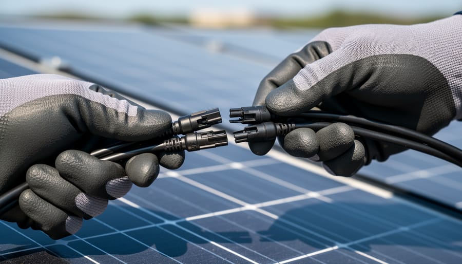
Locate the positive (+) MC4 connector extending from your first solar panel and the negative () MC4 connector from your second panel. These connectors are designed to snap together, positive from panel one must connect to negative from panel two.
Grasp both connectors firmly and align them so the male connector slides into the female connector. You’ll hear and feel a distinct click when they lock together properly. Don’t force it; MC4 connectors only fit one way. If there’s resistance, you’re likely trying to connect two male or two female ends.
Once clicked together, give the connection a gentle tug to verify it’s secure. A properly locked MC4 connection won’t pull apart easily, this is intentional for weather resistance and safety.
If your panels use junction boxes instead of MC4 connectors, you’ll need to open each box and connect the appropriate wires using wire nuts or terminal blocks rated for outdoor DC use. Strip approximately half an inch of insulation, twist the positive wire from panel one with the negative wire from panel two clockwise, then secure with an appropriately sized wire nut or terminal connector.
Step 4: Route the Output Cables
After connecting the two panels together, you now have two free leads that form your series string output. The negative cable from your first panel and the positive cable from your second panel are what you’ll route to your charge controller or inverter.
Determine the shortest, safest path from your panels to your equipment. Avoid routing cables where they’ll be stepped on, pinched by moving parts, or exposed to sharp edges. If running cables across a roof or through walls, use conduit to protect against physical damage and UV exposure.
Leave enough slack at both ends, about 12 inches at the panel side and 18 inches at the controller side. This prevents tension on the connections and makes future maintenance easier. Don’t pull cables tight, as thermal expansion and contraction can stress the connections over time.
Bundle the positive and negative cables together using UV-resistant cable ties every 12 to 18 inches to keep them organized and prevent wind damage.
Step 5: Secure All Connections
After making your connections, verify that each MC4 connector has clicked fully into place. You should hear and feel a distinct snap when the connector locks. Try gently tugging on each connection, it shouldn’t pull apart without pressing the release tab.
Check that no bare wire is exposed at any connection point. The rubber seals inside MC4 connectors must sit flush against the cable insulation to maintain weatherproofing. If you see any copper showing, disconnect and re-crimp that terminal.
Use UV-resistant cable ties every 12 to 18 inches along wire runs to prevent wind damage and rubbing. Don’t overtighten, leave enough slack for thermal expansion and contraction. Where cables enter junction boxes or connectors, create a small drip loop so water runs away from the connection rather than pooling around it.
Step 6: Final Wire Routing and Organization
Route your cables along the mounting rails or panel frames using UV-resistant zip ties every 12-18 inches. Keep wires away from sharp metal edges that could wear through insulation over time. If running cables across a roof surface, use conduit or protective sleeving rated for outdoor exposure. Leave a small service loop, about 6 inches of slack, near each connection point so you can access terminals without straining the cables during future maintenance or troubleshooting.
Bundle series connection wires separately from other system cables, and label both ends clearly (“Series String 1 – Positive” and “Series String 1 – Negative”). This saves confusion later when you’re expanding your system or diagnosing issues. Check that no cables dangle loosely or touch the roof surface directly where heat buildup could accelerate degradation.
Testing and Verifying Your Series Connection
Before you connect your newly wired panels to your charge controller or inverter, you need to verify the series connection is working correctly. This testing step catches wiring errors before they cause system damage and confirms your panels are producing the expected voltage for your setup.
Start by covering both panels completely with opaque material or waiting until dusk when there’s minimal sunlight. This prevents the panels from generating full power while you’re handling exposed wires, reducing shock risk. Once covered, locate the two output wires from your series string, the negative lead from the first panel and the positive lead from the second panel.
Set your multimeter to DC voltage mode, selecting a range that accommodates your expected output. If each panel is rated at 18 volts, you should see approximately 36 volts from your series connection. Touch the red multimeter probe to the positive output wire and the black probe to the negative output wire. The reading should equal the sum of your individual panel voltages, confirming the series connection is functioning properly.
Next, verify polarity by checking that your positive lead shows positive voltage and your negative lead completes the circuit correctly. If the multimeter displays a negative number, your probes are reversed, but the connection itself is fine, just swap probe positions.
For a continuity check, set your multimeter to resistance or continuity mode. With panels still covered, test between connection points to ensure there are no breaks in the wiring path. You should see very low resistance (near zero ohms) between connected terminals.
Once you’ve confirmed correct voltage output and polarity, document your readings. These baseline numbers help you monitor system performance over time and justify the residential solar cost by proving your installation is delivering the expected power output from day one.
Connecting Your Series String to Your Solar System
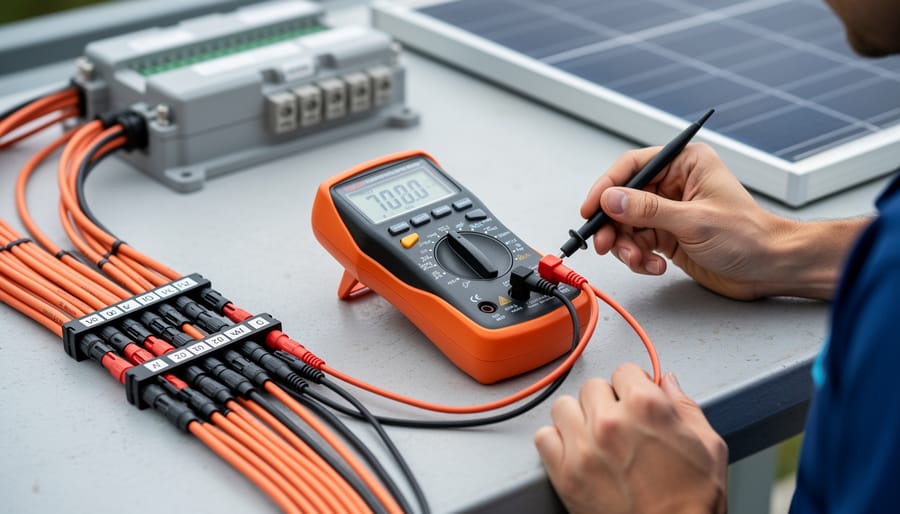
With your two panels successfully wired in series and tested, you’re ready to connect them to your solar system. This final integration step brings your panels into the complete power chain.
Before making any connections, double-check your system’s voltage compatibility. Your charge controller or inverter should have a clearly labeled input voltage range. Your series string’s combined voltage (which you verified with your multimeter) must fall within this range. For example, two 100-watt panels at 18 volts each produce 36 volts in series, ensure your equipment accepts this input.
Most charge controllers and inverters use MC4 connectors or terminal blocks. Match the polarity carefully: connect your series string’s positive output to the positive input terminal, and negative to negative. Never reverse these connections, even briefly. If your equipment uses terminal blocks instead of MC4 connectors, you’ll need to crimp ring terminals onto your panel leads and secure them with the appropriate torque settings listed in your equipment manual.
Once physically connected, power up your system gradually. Many charge controllers display input voltage immediately, this confirms your panels are communicating correctly. Watch for any error codes or unusual readings during the first few minutes of operation.
If your system includes battery storage, your charge controller will begin managing the charging process based on battery voltage and chemistry. Grid-tied systems will start feeding power through the inverter once it verifies grid parameters.
Document your final voltage and current readings under load for future troubleshooting reference.
Common Questions About Series Solar Panel Wiring
The process of wiring solar panels in series can raise practical questions about compatibility, performance, and future expansion. Understanding these common concerns helps you troubleshoot issues and make informed decisions about your solar system configuration.
Can I wire two panels with different wattages in series?
You can physically connect panels with different wattages, but the system will only produce power at the rate of the weakest panel’s current output. For example, if you connect a 300-watt panel (producing 9 amps) with a 200-watt panel (producing 6 amps), your series string will be limited to 6 amps, essentially wasting the extra capacity of the larger panel.
What happens if one panel gets shaded in a series connection?
When one panel in a series string is shaded, it acts as a bottleneck that reduces power output for the entire string. The shaded panel produces less current, and since current remains constant throughout a series circuit, the whole system drops to match that lower output, potentially reducing total production by 50% or more depending on shading severity.
Can I add more panels to my series string later?
You can expand a series string by adding more panels, but you must ensure the total voltage doesn’t exceed your charge controller or inverter’s maximum input voltage rating. Most systems have specific voltage limits, so check your equipment specifications before adding panels.
Why don’t my voltage readings add up to what I expected?
If your multimeter shows lower-than-expected voltage, verify that you’re testing under actual sunlight (not cloudy conditions), check that all MC4 connections are fully locked, and confirm you haven’t accidentally created a parallel connection instead of series. Voltage should equal the sum of both panel voltages when properly connected in full sun.
Beyond these core questions, consider the impact of panel orientation when troubleshooting performance issues. Panels wired in series should ideally face the same direction and angle to receive similar light intensity throughout the day. Mismatched orientations create the same bottleneck effect as shading, where the panel receiving less sunlight limits the output of the entire string.
Temperature differences between panels can also affect performance, though less dramatically than shading. A panel operating 20 degrees hotter than its partner may produce slightly different voltage, but the effect is usually minor compared to shading or physical connection problems.
If you’re experiencing persistent issues where your series connection underperforms despite following all steps correctly, the problem may lie with mismatched panel specifications that aren’t immediately obvious. Check not just wattage, but also the voltage ratings under standard test conditions. Panels with significantly different voltage characteristics won’t perform well together even if their wattage ratings seem compatible.
For North Carolina installations, seasonal shading patterns matter. A connection that works perfectly in summer might struggle in winter when the sun angle changes and nearby trees cast different shadows. Plan your series configuration with year-round conditions in mind, or be prepared to adjust panel positions as seasons change.
Wiring two solar panels in series is a straightforward way to boost voltage output and match your system’s requirements, provided you’ve measured your power needs accurately and followed proper connection procedures. By connecting positive to negative, you create a single string that delivers higher voltage while maintaining the same amperage, making it ideal for many residential and small commercial installations.
The key to success? Measure twice, connect once. Take time to verify your panel specifications, understand how panels work within your specific system, and double-check every connection with a multimeter before bringing your array online.
At Solar Installer Ninja, we’re committed to empowering the North Carolina community with the knowledge and resources to make informed solar decisions. We prioritize American-made products and believe education is the foundation of successful renewable energy adoption.
If you’re uncertain about any step in the process or prefer professional installation, our team is here to help. Reach out to discuss your solar project, we’ll ensure your system is wired safely, performs optimally, and meets your long-term energy goals.
